
Low Pressure Carburization Process Improvement for a Ring Gear
Introduction
Low pressure carburization (LPC) processes are becoming more widespread throughout industry due to the reduced cycle times and the control over the carbon profile through the case. Unlike gas carburization, which utilizes a constant carbon potential to maintain the available carbon on the part surface at a specific value, LPC utilizes boost and diffuse steps. A boost step involves the temporary addition of a carbon carrying gas to the furnace, usually acetylene, to increase the surface carbon to the saturation limit of austenite. If not properly controlled, the carbon available for diffusion can well exceed the saturation limit, creating unfavorable carburizing conditions. After a requisite amount of time has passed, generally one to several minutes, the carbon carrying gas is evacuated from the chamber. The carbon that was deposited on the surface during the boost step is then allowed to diffuse into the part, reducing the surface carbon. These two steps are then repeated until the required case depth and carbon profile are achieved.
For steel alloys that do not contain a significant amount of strong carbide forming elements, this process can be relatively easy to control. However, with the advent of high strength steels for the aerospace industry, most of which contain substantial amounts of strong carbide forming elements, such as chromium, molybdenum, and vanadium, the LPC process can be extremely challenging to control. These elements bond with the carbon deposited on the surface to form primary carbides, which if not properly dissolved can damage fatigue performance. Furthermore, long boost times, as well as very short diffuse times, can lead to the thermodynamic stabilization of these primary carbides.
While Fick’s Second Law describes the diffusion of carbon through a low alloy steel with reasonable accuracy, the same is not true of medium and high alloy steels. This is due to the presence of primary carbides forming and dissolving during the LPC process. When the boost step is occurring, the primary carbides take carbon away from the austenite solution, allowing more carbon to enter the solid solution from the surface. During the diffuse step, as the carbon that is in solid solution diffuses into the part, reducing the carbon in austenite, the primary carbides can dissolve to provide more carbon to the solid-state solution. If the primary carbides are not allowed to fully dissolve or shrink to a significantly small size before the next boost step begins, they will continue to grow. In order to properly predict the carbon profile of medium and high alloy steels, the primary carbide formation and dissolution must be considered. The heat treatment simulation software DANTE has this capability.
The following is a case study for the redesign of an LPC schedule for a ring gear using the DANTE heat treatment simulation software. The original LPC schedule, consisting of six boost-diffuse steps, was producing too many primary carbides during the process, and consequently, rolling contact fatigue performance was diminished.
Geometry and Model
Part: Ring Gear
- Material: Ferrium C64
- Outer Diameter: 5.5 inches
- Inner Diameter: 4.5 inches
- Height: 0.060 inches
- Number of Teeth: 40
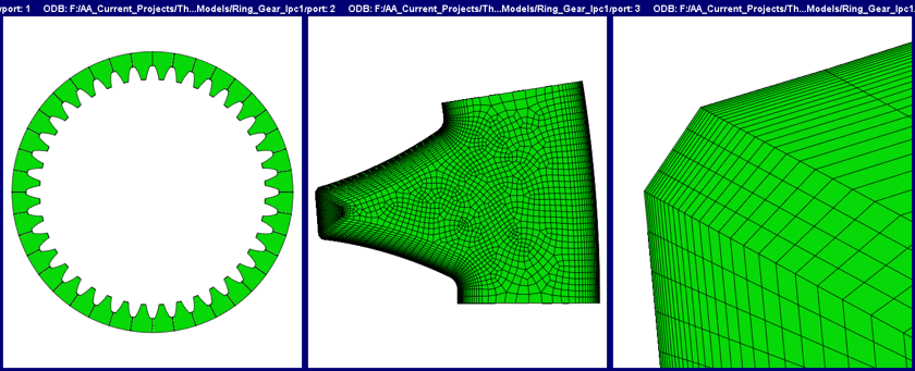
Model: Single Tooth
- Cyclic Symmetry: Carbon boundary conditions act uniformly on all teeth
- Number of Elements: 233,850 linear hexagonal
- Number of Nodes: 245,055
- Higher mesh density near surface to capture steep carbon gradients
LPC Experiments vs. Prediction
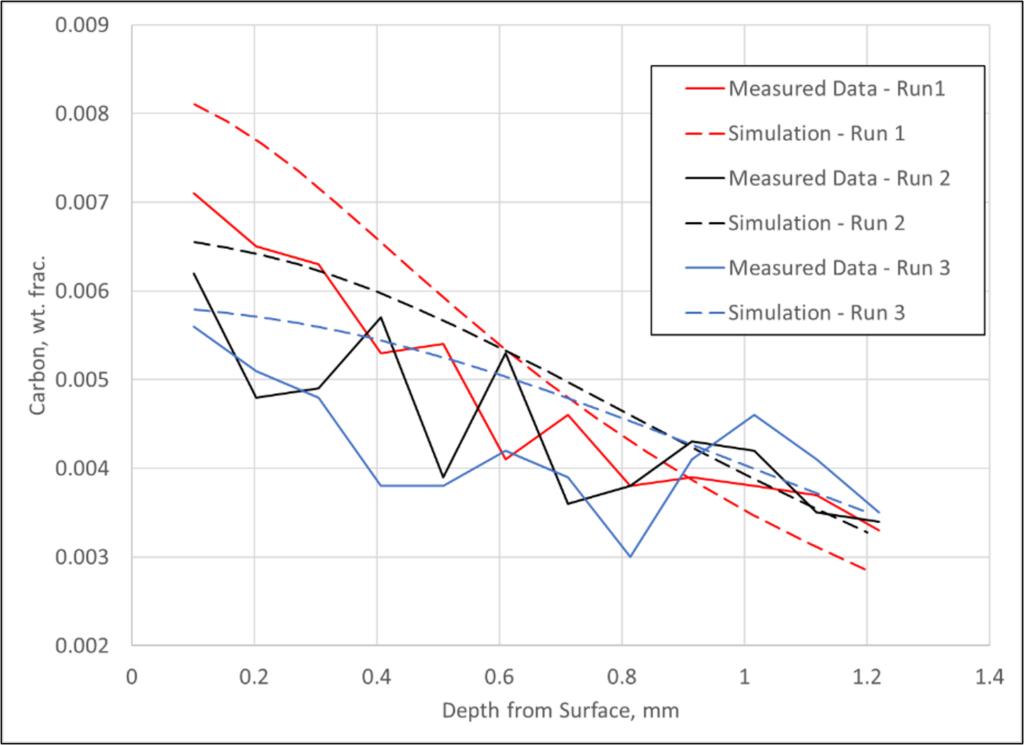
- Experimental data versus DANTE prediction for 3 LPC runs
- LPC experiments conducted using a cylinder with a 4-inch OD and a 4-inch height made of Ferrium C64
- 3 different boost-diffuse schedules executed
- 6 boost-diffuse steps
- All 3 schedules used the same first 11 steps
- Final diffuse time increased for each run, with Run1 have the shortest and Run 3 having the longest
- LECO used to measure the carbon profile of the test coupons
- DANTE model parameters for carbon diffusivity, carbide formation, and carbide dissolution fit from experimental data
- Simulation matches experimental data reasonably well

Original Process Model Results
- Case depth originally designed for 0.75 mm (0.030 inch) on the flank of the tooth, with a carbon value of 0.3% resulting in a hardness value of 50 HRC for Ferrium C64 when tempered at 495° C (925° F).
- Contour plot shows all carbon, the carbon in the austenite matrix and the carbon in primary carbide form, at the end of the process for the baseline model
- Areas above 0.011 carbon contain primary carbides
- Tip contains a high amount of primary carbides
- Line plot shows the carbon in the austenite matrix (Carbon) and the carbon in primary carbide form (Carbon in Carbide) from the surface of the flank towards the core for the baseline model at the end of the process
- Carbides present at a depth of 0.25 mm (0.010 inch)
- Case depth ~0.35 mm deeper than required

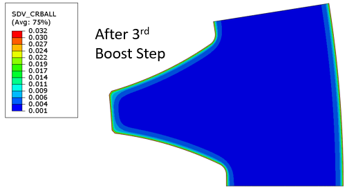
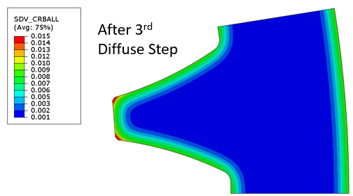
- Contour plot shows all carbon, the carbon in the austenite matrix and the carbon in primary carbide form, at the end of the 3rd boost and diffuse steps
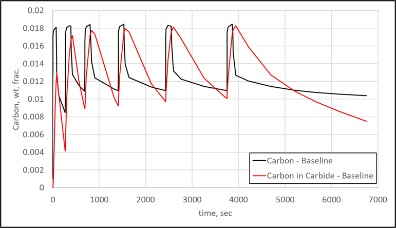
- Line plot shows the predicted carbon in the austenite matrix (Carbon) and the carbon in primary carbide form (Carbon in Carbides) at the surface of the flank for the baseline model over the total time of the process
- Carbides formed during the first boost step continue to grow as the process progresses, indicated by the increasing carbon in carbide
- Final diffuse not long enough to fully dissolve carbides
Redesigned Process Model Results
- To ensure the primary carbides dissolve completely before hardening, a new schedule was developed with the aim of reducing the carbon in primary carbide form
- 3 boost-diffuse steps were removed, and the diffuse times increased substantially
- Increase in diffuse time increased the schedule by approximately one-half hour, which is acceptable given the positive results
- Contour plot shows all carbon, the carbon in the austenite matrix and the carbon in primary carbide form, at the end of the process for the redesigned process model
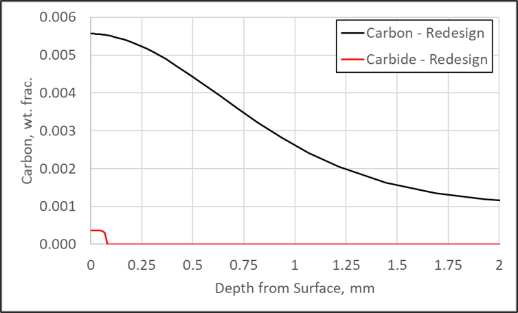
- Line plot shows the carbon in the austenite matrix (Carbon) and the carbon in primary carbide form (Carbon in Carbide) from the surface of the flank towards the core for the redesigned model at the end of the process
- Small carbides (negligible) at a depth of 0.1 mm (0.004 inch)
- Easily removed with finish grinding operation
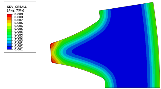
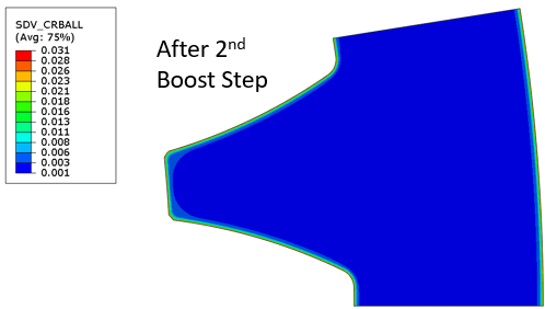
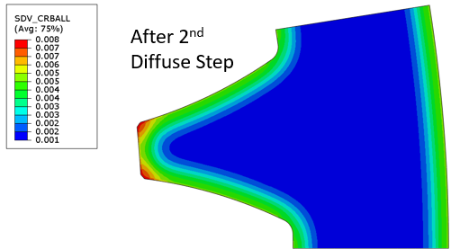
- Contour plot shows all carbon, the carbon in the austenite matrix and the carbon in primary carbide form, at the end of the 2nd boost and diffuse steps for the redesigned process
- Primary carbides are nearly fully dissolved, even in the tip (carbon is higher, but it is not in carbide form), at the end of the diffuse step
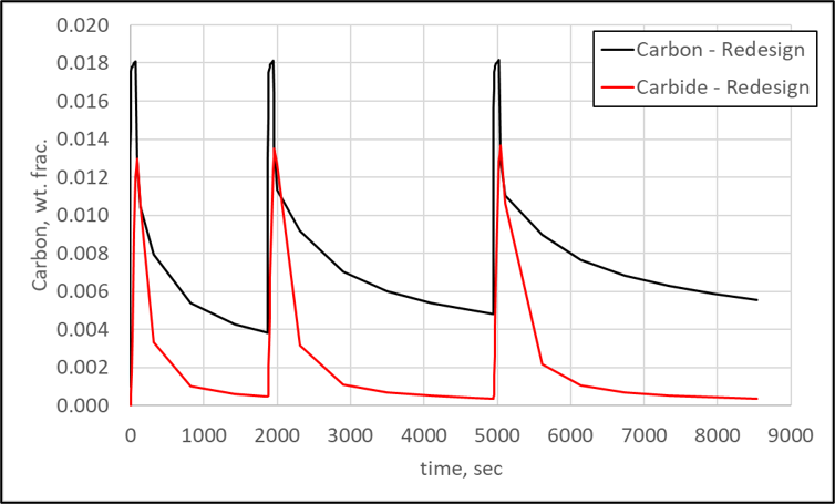
- Line plot shows the predicted carbon in the austenite matrix (Carbon) and the carbon in primary carbide form (Carbon in Carbides) at the surface of the flank for the redesigned model over the total time of the process
- Carbides are nearly fully dissolved after each diffuse step
Summary
- DANTE carburization model parameters for carbon diffusivity, carbide formation, and carbide dissociation fit from experimental data
- Any steel alloy and LPC equipment can be fit to the DANTE carburization model
- DANTE used to successfully predict the results of a low-pressure carburization process that was resulting in poor part performance during rolling contact fatigue
- Model showed that large primary carbides exist at a depth of 0.25 mm (0.010 inch)
- Model showed that the carbides do not have time to dissolve during the boost steps
- DANTE used to successfully redesign the boost-diffuse schedule to improve rolling contact fatigue performance
- Model showed that small primary carbides (negligible) exist at a depth of 0.1 mm (0.004 inch)
- Model showed that the carbides nearly fully dissolve during the diffuse steps
- Small carbides removed during the finish grinding operation
- Rolling contact fatigue performance improved due to the absence of primary carbides near the surface
- DANTE not limited to Ferrium C64 with respect to primary carbide formation during LPC
- Continually updating the material database with carbide behavior for different alloys
- Continually validating the model with experiments
Student/Trial License
Get hands-on experience with DANTE. Our student and trial license offers full access to heat treatment modeling tools so you can learn, experiment, and explore real-world simulations.

resources

Research that drives our decisions
Explore our peer-reviewed studies and technical papers developed over the past 50 years in the industry by our engineers.

Talk with our experts
Have a project or a question about heat treating? Connect with our engineers for to discuss how DANTE can fit into your workflow.

tools for heat treatment modeling
See how the DANTE suite enables engineers to simulate quenching, distortion, hardness, stress, and metallurgical phases

Proven industry results
Explore our case studies showing how DANTE FEA predicts distortion, hardness, phase changes, and residual stress.