Bearing Ring Cracking in Press Quenching
Challenge
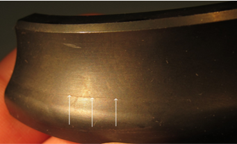
The basis of this study is a 4” OD bearing ring, made of AISI 52100 steel. A large number of these bearing rings were failing during the press quenching process, as seen in the table. Large circumferential cracks could be seen in the bearing race in over half of the parts after quench and temper. The quick solution was to pulse the die during the quench to periodically ease the pressure on the part. Quickly relieving and reapplying the load allowed the part to contract more naturally, while still maintaining the desired final shape. When pulsing was not used, frictional forces from the upper and lower dies contacting the part added stress to the process by not allowing the part to contract freely.
Press quenching is a highly specialized quench hardening technique for components which cannot be held in tolerance during a standard free quenching operation, such as spiral bevel gears and bearing races used in automotive and aerospace applications. The press quench operation aims to control the distortion of the part by applying loads to critical locations of the component while it is being rapidly cooled. The quench machines are highly adaptable to handle any given geometry and distortion mode; such as flatness, taper, and out-of-round. The quench flow rate can be further controlled by rotating the slotted rings to either constrict or liberate the flow of quenchant to different areas around the part. The restricting elements, coupled with thermal and transformation induced dimensional changes, create in-process and residual stresses, adding complexity to the existing process sensitivities present in other quenching processes.
In order to reduce the impact of in-process stresses and distortion, heat should be extracted from the part as uniformly as possible. This can be a challenge when part geometry is not symmetric, as larger mass/lower surface area regions will cool slower than lower mass/higher surface area regions. This leads to non-uniformities in phase transformation timing and stresses, and consequently distortion. The press quench tooling is designed to reduce the displacement caused by these non-uniformities, but it likewise has an impact on residual stresses and in-process stress magnitudes.

Model Definition
In order to have a full understanding of the mechanisms at work in the stated problem, an FE model was developed to examine several process sensitivities. A fine mesh was applied to a 2D, axisymmetric cross section of the bearing race to accurately capture the heat transfer and stresses leading to the failures. The figure to the right shows the meshed FE model consisting of 9,367 nodes and 9,188 linear elements. The table below the figure shows the chemistry for AISI 52100 steel. The DANTE heat treatment simulation software has 52100 steel in its material database and was used for the following analyses.

Frictional Effects
Frictional forces from the press quenching process will be examined, and how they affect residual stresses. As the part cools and shrinks, there will be some friction between the part and the quench dies as the dies work to keep the bearing race flat. In some cases the part will stick to the quench dies, impeding the part’s ability to contract naturally. This can lead to undesirable stresses in the part during the quench process. In this study, six different friction conditions will be evaluated. Three conditions will use a constant friction coefficient and they are:
- 0.5
- 0.2
- 0.05
Several conditions of sticking between the dies and the part will also explored:
- Upper die to top of part
- Lower die to bottom of part
- Upper and lower dies
The sticking was modeled by fixing the selected areas in the radial direction, restraining the bearing race’s natural contraction, as if the part were stuck to the quench die. To the right is the die placement and loads prescribed by these conditions

Quench Rate Effects
In addition to the six friction conditions, four quench rates were also examined to evaluate their effect on stress development. They are:
- Standard Press Quench profile, used as a baseline representing the current process
- High Flow Press Quench
- Low Flow Press Quench
- Reduced Quench On Inner Ring Surface
The three additional quench rates were modeled as factors of the baseline. The plot of each of these heat transfer coefficients vs. temperature can be viewed to the right. Bottom right is the full 9-case test matrix used for this parametric study.
The standard, low, and high quench rates are evaluated with the lowest friction coefficient, while the standard quench rate is used for the two higher friction coefficients and the sticking conditions. The final case uses the lowest friction coefficient, along with a reduced ID quench rate and a standard quench rate on the OD.
Friction Sticking Results
The contours below demonstrate the effect of the three sticking conditions. A few observations from the contours:
- The bottom die sticking exhibits the largest in-process stress: 882 MPa with top die sticking also and 860 MPa without the top die sticking.
- Top die sticking alone presents a max in-process stress of only 680 MPa, slightly higher than the standard quench rate model.
- Comparing the max in-process stress of the bottom die sticking models to the standard quench model, the sticking model stress is over 200 MPa greater in magnitude.
- This shows the importance of pulsing and its significant effect on stress formation. The mechanism behind the large stress formation in the bearing race is due to a late phase transformation in the larger mass region of the ring. The volume expansion of this phase, coupled with frictional sticking at the base, transfers the stress concentration to the bearing race.

Vary Quench Results
The peak in-process stress, and residual stress states of the four quench rate conditions are shown in the contours to the right. A few observations from the figures:
- All three of the equal ID and OD quench rates show an in-process spike of tensile stresses in the region where the cracks were forming.
- The high flow quench displayed the highest tensile stress at 746 MPa, occurring 12 seconds into the quench
- The low flow max tensile stress was 400 MPa, occurring 22 seconds into the quench.
A few closing remarks on the quench rate sensitivity study:
- While varying the quench rate does show a change in the magnitude of in-process tensile stresses, the location of this stress does not change if the quench rate on the ID and OD are equivalent.
- The last quench case, however, shifts the max in-process stress to the bottom of the part due to slower cooling on the ID, and reducing the problem region tensile stress significantly.
- The standard quench rate in-process stress is not likely to cause the cracking consistency seen.

Results
The contours below demonstrate the effect of the three sticking conditions. A few observations from the contours:
- The bottom die sticking exhibits the largest in-process stress: 882 MPa with top die sticking also and 860 MPa without the top die sticking.
- Top die sticking alone presents a max in-process stress of only 680 MPa, slightly higher than the standard quench rate model.
- Comparing the max in-process stress of the bottom die sticking models to the standard quench model, the sticking model stress is over 200 MPa greater in magnitude.
- This shows the importance of pulsing and its significant effect on stress formation. The mechanism behind the large stress formation in the bearing race is due to a late phase transformation in the larger mass region of the ring. The volume expansion of this phase, coupled with frictional sticking at the base, transfers the stress concentration to the bearing race.

The table shows the maximum in-process and maximum residual stress at the problem location for each of the nine testing conditions. The following conclusions can be drawn from this work:
- An increase in the friction coefficient increases the max stress magnitudes only slightly.
- If the part gets stuck to the bottom quench die, a dramatic increase of in-process stresses occur.
- The high in-process stress when the bottom die sticks is expected to cause cracking issues, particularly with any surface stress raisers.
- Varying the quench rate shows some change in stress levels, with lower quench rates giving lower max stresses, and higher quench rates producing larger magnitudes of stress.

Student/Trial License
Get hands-on experience with DANTE. Our student and trial license offers full access to heat treatment modeling tools so you can learn, experiment, and explore real-world simulations.

resources

Research that drives our decisions
Explore our peer-reviewed studies and technical papers developed over the past 50 years in the industry by our engineers.

Talk with our experts
Have a project or a question about heat treating? Connect with our engineers for to discuss how DANTE can fit into your workflow.

tools for heat treatment modeling
See how the DANTE suite enables engineers to simulate quenching, distortion, hardness, stress, and metallurgical phases

Proven industry results
Explore our case studies showing how DANTE FEA predicts distortion, hardness, phase changes, and residual stress.